
Honda Fit/Jazz - Fuel and Emissions System Description (5MT-KM/KP)
Fuel and Emissions System Description
Electronic Control System
The functions of the fuel and emission control systems are managed by the Engine Control Module (ECM).
Fail-safe Function
When an abnormality occurs in a signal from a sensor, the ECM ignores that signal and assumes a pre-programmed value for that sensor that allows the engine to continue to run.Back-up Function
When an abnormality occurs in the ECM, the injectors are controlled by a back-up circuit independent of the system to permit minimal driving.Self-diagnosis
When an abnormality occurs in the signal from a sensor, the ECM supplies ground for the Malfunction Indicator Lamp (MIL) and stores the Diagnostic Trouble Code (DTC) in erasable memory. When the ignition is first turned on, the ECM supplies ground for the MIL for 2 seconds to check the MIL bulb condition.Two Driving Cycle Detection Method
To prevent false indications, the ‘‘two driving cycle detection method'' is used for some self-diagnostic functions. When an abnormality occurs, the ECM stores it in its memory. When the same abnormality recurs after the ignition switch is turned OFF and ON (II) again, the ECM informs the driver by turning on the MIL.Self Shut Down Mode (SSD)
After the ignition switch is turned off, ECM stays ON (Up to 10 seconds).If the ECM connector is disconnected during this mode, ECM may be damaged.
If you need to disconnet the ECM connector, disconnect the negative cable from the battery, or wait for 10 seconds after turning the ignition switch off.
ECM Inputs and Outputs at Connector No. 1 (9P)
 NOTE: Standard battery voltage is 12 V.
| ECM Terminal number | Pin Box Terminal number | Wire color | Terminal name | Description | Signal |
|---|---|---|---|---|---|
| 4 | 4 | BRN | PG1 (POWER GROUND) | Ground for ECM circuit | Less than 1.0 V at all times |
| 5 | 5 | BRN | PG2 (POWER GROUND) | Ground for ECM circuit | Less than 1.0 V at all times |
| 7 | 7 | WHT/RED | UBD (POWER SOURCE) | Power source for ECM circuit | Battery voltage at all times |
| 8 | 8 | BRN/YEL | LG3 (LOGIC GROUND) | Ground for ECM circuit | Less than 1.0 V at all times |
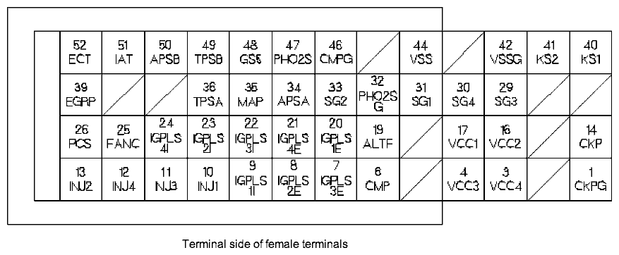
ECM Inputs and Outputs at Connector No. 3 (52P)
 NOTE: Standard battery voltage is 12 V.
| ECM Terminal number | Pin Box Terminal number | Wire color | Terminal name | Description | Signal |
|---|---|---|---|---|---|
| 1 | 30 | BRN/YEL | CKPG (CRANKSHAFT POSITION (CKP) SENSOR GROUND) | Ground for CKP sensor | Less than 1.0 V at all times |
| 3 | 32 | BLU/RED | VCC4 (SENSOR VOLTAGE) | Provides sensor voltage | With ignition switch ON (II): about 5 V With ignition switch OFF: 0 V |
| 4 | 33 | YEL/GRN | VCC3 (SENSOR VOLTAGE) | Provides sensor voltage | With ignition switch ON (II): about 5 V With ignition switch OFF: 0 V |
| 6 | 35 | GRN | CMP (CAMSHAFT POSITION (CMP) SENSOR) | Detects CMP sensor signal | With engine running: pulses |
| 7 | 36 | WHT/BLK | IGPLS3E (No. 3 REAR IGNITION COIL PULSE) | Drives No. 3 rear ignition coil | With ignition switch ON (II): 0 V With engine running: pulses |
| 8 | 37 | WHT/GRN | IGPLS2E (No. 2 REAR IGNITION COIL PULSE) | Drives No. 2 rear ignition coil | |
| 9 | 38 | WHT | IGPLS1I (No. 1 FRONT IGNITION COIL PULSE) | Drives No. 1 front ignition coil | |
| 10 | 39 | BRN | INJ1 (No. 1 INJECTOR) | Drives No. 1 injector | At idle: duty controlled |
| 11 | 40 | BLU | INJ3 (No. 3 INJECTOR) | Drives No. 3 injector | |
| 12 | 41 | YEL | INJ4 (No. 4 INJECTOR) | Drives No. 4 injector | |
| 13 | 42 | RED | INJ2 (No. 2 INJECTOR) | Drives No. 2 injector | |
| 14 | 43 | BLU | CKP (CRANKSHAFT POSITION (CKP) SENSOR) | Detects CKP sensor signal | With engine running: pulses |
| 16 | 45 | YEL/BLU | VCC2 (SENSOR VOLTAGE) | Provides sensor voltage | With ignition switch ON (II): about 5 V With ignition switch OFF: 0 V |
| 17 | 46 | YEL/RED | VCC1 (SENSOR VOLTAGE) | Provides sensor voltage | With ignition switch ON (II): about 5 V With ignition switch OFF: 0 V |
| 19 | 48 | WHT/RED | ALTF (ALTERNATOR FR SIGNAL) | Detects alternator FR signal | With engine running: 0 V-5 V (depending on electrical load) |
| 20 | 49 | WHT | IGPLS1E (No. 1 REAR IGNITION COIL PULSE) | Drives No. 1 rear ignition coil | With ignition switch ON (II): 0 V With engine running: pulses |
| 21 | 50 | WHT/BLU | IGPLS4E (No. 4 REAR IGNITION COIL PULSE) | Drives No. 4 rear ignition coil | |
| 22 | 51 | WHT/BLK | IGPLS3I (No. 3 FRONT IGNITION COIL PULSE) | Drives No. 3 front ignition coil | |
| 23 | 52 | WHT/GRN | IGPLS2I (No. 2 FRONT IGNITION COIL PULSE) | Drives No. 2 front ignition coil | |
| 24 | 53 | WHT/BLU | IGPLS4I (No. 4 FRONT IGNITION COIL PULSE) | Drives No. 4 front ignition coil | |
| 25 | 54 | GRN | FANC (RADIATOR FAN CONTROL) | Drives radiator fan relay | With radiator fan running: about 0 V With radiator fan stopped: battery voltage |
ECM Inputs and Outputs at Connector No. 3 (52P)
NOTE: Standard battery voltage is 12 V.| ECM Terminal number | Pin Box Terminal number | Wire color | Terminal name | Description | Signal |
|---|---|---|---|---|---|
| 26 | 55 | YEL/BLU | PCS (EVAPORATIVE EMISSION (EVAP) CANISTER PURGE VALVE) | Drives EVAP canister purge valve | With engine running, engine coolant below 40°C (104°F): battery voltage With engine running, engine coolant above 40°C (104°F): duty controlled |
| 29 | 58 | GRN/BLK | SG3 (SENSOR GROUND) | Sensor ground | Less than 1.0 V at all times |
| 30 | 59 | GRN/BLK | SG4 (SENSOR GROUND) | Sensor ground | Less than 1.0 V at all times |
| 31 | 60 | GRN/WHT | SG1 (SENSOR GROUND) | Sensor ground | Less than 1.0 V at all times |
| 32 | 61 | GRN/YEL | PHO2SG (PRIMARY HEATED OXYGEN SENSOR (PRIMARY HO2S, SENSOR 1) GROUND) | Ground for primary HO2S (sensor 1) | Less than 1.0 V at all times |
| 33 | 62 | GRN/BLK | SG2 (SENSOR GROUND) | Sensor ground | Less than 1.0 V at all times |
| 34 | 63 | GRN | APSA (ACCELERATOR PEDAL POSITION (APP) SENSOR A) | Detects APP sensor A signal | With ignition switch ON (II) and accelerator pedal pressed: 4.1 V With ignition switch ON (II) and accelerator pedal released: 0.6 V |
| 35 | 64 | GRN/RED | MAP (MANIFOLD ABSOLUTE PRESSURE (MAP) SENSOR) | Detects MAP sensor signal | With ignition switch ON (II): about 3 V At idle: about 1.0 V (depending on engine speed) |
| 36 | 65 | BLU | TPSA (THROTTLE POSITION (TPS) SENSOR A) | Detects TPS sensor A signal | With ignition switch ON (II) and throttle fully open: 4.7 V With ignition switch ON (II) and throttle fully closed: 0.1 V |
| 39 | 68 | WHT/BLK | EGRP (EXHAUST GAS RECIRCULATION (EGR) VALVE POSITION SENSOR) | Detects EGR valve position sensor signal | With engine running: 1.2 V-2.0 V (depending on EGR valve lift) |
| 40 | 69 | YEL | KS1 (KNOCK SENSOR) | Detects knock sensor signal | With engine knocking: pulses |
| 41 | 70 | GRY/RED | KS2 (KNOCK SENSOR) | Ground for knock sensor | Less than 1.0 V at all times |
| 42 | 71 | BLK | VSSG (VEHICLE SPEED SENSOR (VSS) GROUND) | Ground for VSS | Less than 1.0 V at all times |
| 44 | 73 | WHT/GRN | VSS (VEHICLE SPEED SENSOR (VSS)) | Detects VSS signal | With ignition switch ON (II) and front wheels rotating: cycles 0 V-about 5 V or battery voltage |
| 46 | 75 | BRN/YEL | CMPG (CAMSHAFT POSITION (CMP) SENSOR GROUND) | Ground for CMP sensor | Less than 1.0 V at all times |
| 47 | 76 | WHT | PHO2S (PRIMARY HEATED OXYGEN SENSOR (PRIMARY HO2S) SENSOR 1) | Detects primary HO2S sensor (sensor 1) signal | With throttle fully opened from idle with fully warmed up engine: about 0.6 V With throttle quickly closed: below 0.4 V |
ECM Inputs and Outputs at Connector No. 3 (52P)
NOTE: Standard battery voltage is 12 V.| ECM Terminal number | Pin Box Terminal number | Wire color | Terminal name | Description | Signal |
|---|---|---|---|---|---|
| 48 | 77 | GRN/BLK | SG5 (SENSOR GROUND) | Sensor ground | Less than 1.0 V at all times |
| 49 | 78 | YEL | TPSB (THROTTLE POSITION (TPS) SENSOR B) | Detects TPS sensor B signal | With ignition switch ON (II) and throttle fully open: 4.9 V With ignition switch ON (II) and throttle fully closed: 0.1 V |
| 50 | 79 | RED | APSB (ACCELERATOR PEDAL POSITION (APP) SENSOR B) | Detects APP sensor B signal | With ignition switch ON (II) and accelerator pedal pressed: 2.3 V With ignition switch ON (II) and accelerator pedal released: 0.2 V |
| 51 | 80 | RED/YEL | IAT (INTAKE AIR TEMPERATURE (IAT) SENSOR) | Detects IAT sensor signal | With ignition switch ON (II): about 0.1-4.8 V (depending on intake air temperature) |
| 52 | 81 | RED/WHT | ECT (ENGINE COOLANT TEMPERATURE (ECT) SENSOR) | Detects ECT sensor signal | With ignition switch ON (II): about 0.1-4.8 V (depending on engine coolant temperature) |
ECM Inputs and Outputs at Connector No. 4 (40P)
 NOTE: Standard battery voltage is 12 V.
| ECM Terminal number | Pin Box Terminal number | Wire color | Terminal name | Description | Signal |
|---|---|---|---|---|---|
| 1 | 82 | GRN/WHT | FUP (FUEL INJECTION SIGNAL) | Sends fuel injection signal to gauge assembly | With ignition switch ON (II): pulses |
| 2 | 83 | GRN | MTRTW | Sends engine coolant temperature signal | With ignition switch ON (II): pulses |
| 5 | 86 | RED/WHT | K-LINE | Sends and receives HDS signal | With ignition switch ON (II): pulses or battery voltage |
| 8 | 89 | GRN/YEL | FPR (FUEL PUMP RELAY) | Drives PGM-FI main relay 2 | 0 V for 2 seconds after turning ignition switch ON (II), then battery voltage |
| 10 | 91 | GRN/ORN | MIL (MALFUNCTION INDICATOR LAMP) | Drives MIL | With MIL turned ON: about 0 V With MIL turned OFF: battery voltage |
| 11 | 92 | RED/YEL | MRLY (PGM-FI MAIN RELAY) | Drives PGM-FI main relay 1 Power source for the DTC memory | With ignition switch ON (II): about 0 V With ignition switch OFF: battery voltage |
| 17 | 98 | BRN/YEL | LG1 (LOGIC GROUND) | Ground for ECM circuit | Less than 1.0 V at al times |
| 18 | 99 | BLU | NEP (ENGINE SPEED PULSE) | Outputs engine speed pulse | With engine running: pulses |
| 19 | 100 | RED | ACC (A/C CLUTCH RELAY) | Drives A/C clutch relay | With compressor ON: about 0 V With compressor OFF: battery voltage |
| 21 | 102 | PNK | SHO2SG (SECONDARY HEATED OXYGEN SENSOR (SECONDARY HO2S), SENSOR 2 GROUND) | Ground for secondary HO2S (sensor 2) | Less than 1.0 V at all times |
| 22 | 103 | WHT/BLU | BKPD (BRAKE PEDAL POSITION SWITCH) | Detects brake pedal position switch signal | With ignition switch ON (II) and brake pedal released: battery voltage With ignition switch ON (II) and brake pedal pressed: about 0 V |
| 23 | 104 | WHT/RED | SHO2S (SECONDARY HEATED OXYGEN SENSOR (SECONDARY HO2S, SENSOR 2) | Detects secondary HO2S (sensor 2) signal | With throttle fully opened from idle with fully warmed up engine: about 0.6 V With throttle quickly closed: below 0.4 V |
ECM Inputs and Outputs at Connector No. 4 (40P)
NOTE: Standard battery voltage is 12 V.| ECM Terminal number | Pin Box Terminal number | Wire color | Terminal name | Description | Signal |
|---|---|---|---|---|---|
| 27 | 108 | BLK/YEL | IG1 (IGNITION SIGNAL) | Detects ignition signal | With ignition switch ON (II): battery voltage With ignition switch OFF: 0 V battery voltage |
| 31 | 112 | BLU/WHT | ACS (A/C SWITCH SIGNAL) | Detects A/C switch signal | With A/C switch ON: 0 V With A/C switch OFF: about 5 V |
| 32 | 113 | BRN | SCS (SERVICE CHECK SIGNAL) | Detects service check signal | With the service check signal shorted with the HDS: about 0 V With the service check signal opened: about 5 V battery voltage |
| 36 | 117 | WHT/BLK | BKSW (BRAKE PEDAL POSITION SWITCH) | Detects brake pedal position switch signal | With brake pedal released: about 0 V With brake pedal pressed: battery voltage |
| 39 | 120 | BRN/YEL | LG2 (LOGIC GROUND) | Ground for ECM circuit | Less than 1.0 V at all times |
ECM Inputs and Outputs at Connector No. 5 (9P)
 NOTE: Standard battery voltage is 12 V.
| ECM Terminal number | Pin Box Terminal number | Wire color | Terminal name | Description | Signal |
|---|---|---|---|---|---|
| 1 | 122 | RED | ETC1 (ELECTRIC THROTTLE CONTROL SYSTEM 1) | Drives throttle actuator | With throttle valve moving: duty controlled With throttle valve not moving: not specified |
| 2 | 123 | GRN | ETC2 (ELECTRIC THROTTLE CONTROL SYSTEM 2) | Drives throttle actuator | With throttle valve moving: duty controlled With throttle valve not moving: not specified |
| 3 | 124 | BLU/RED | EGR (EXHAUST GAS RECIRCULATION (EGR) VALVE) | Drives EGR valve | With EGR operating: duty controlled With EGR not operating: about 0 V |
| 4 | 125 | BLK/WHT | SO2SHTC (SECONDARY HEATED OXYGEN SENSOR (SECONDARY HO2S) HEATER CONTROL) | Drives secondary HO2S heater | With ignition switch ON (II): battery voltage With fully warmed up engine running: duty controlled |
| 5 | 126 | GRN/BLK | EGRG (EXHAUST GAS RECIRCULATION (EGR) VALVE GROUND) | Ground for EGR valve | Less than 1.0 V at all times |
| 7 | 128 | YEL/BLK | IGP1 (POWER SOURCE) | Power source for ECM circuit | With the ignition switch ON (II): battery voltage With the ignition switch OFF: about 0 V |
| 8 | 129 | YEL/BLK | IGP2 (POWER SOURCE) | Power source for ECM circuit | With the ignition switch ON (II): battery voltage With the ignition switch OFF: about 0 V |
| 9 | 130 | BLK/WHT | PO2SHTC (PRIMARY HEATED OXYGEN SENSOR (PRIMARY HO2S) HEATER CONTROL) | Drives primary HO2S heater | With ignition switch ON (II): battery voltage With fully warmed up engine running: duty controlled |
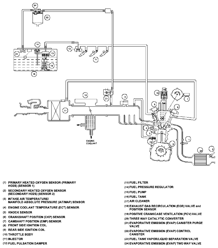
Vacuum Hose Routing

Vacuum Distribution
PGM-FI System
The Programmed Fuel Injection (PGM-FI) system is a sequential multiport fuel injection system.
Air Conditioning (A/C) Compressor Clutch Relay
When the Engine Control Module (ECM) receives a demand for cooling from the A/C system, it delays the compressor from being energized, and enriches the mixture to assure smooth transition to the A/C mode.Alternator Control
The alternator signals the ECM during charging.Barometric Pressure (BARO) Sensor
The BARO sensor is inside the ECM. It converts atmospheric pressure into a voltage signal that modifies the basic duration of the fuel injection discharge.Camshaft Position (CMP) Sensor
The CMP sensor detects the position of the No. 1 cylinder as a reference for sequential fuel injection to each cylinder.
Crankshaft Position (CKP) Sensor
The CKP sensor detects engine speed and determines ignition timing and timing for fuel injection of each cylinder.
Engine Coolant Temperature (ECT) Sensor
The ECT sensor is a temperature dependent resistor (thermistor). The resistor of the thermistor decreases as the engine coolant temperature increases.
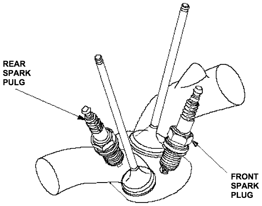
i-DSI System
The ECM controls the ignition phase gap between the front and rear spark plugs in accordance with the engine speed and the vacuum in the intake manifold.
- At idling, both the front and rear spark plugs ignite simultaneously for faster combustion speed and the resulting improvement of the fuel consumption.
- At low speed with low load operation, the ECM advances the ignition timing at the front side spark plug, where the combustion chamber temperature is relatively low, to improve the fuel consumption.
- At low speed with high load operation, ignition timing is advanced at the front side spark plug and it is retarded at the rear side to improve torque while controlling the engine knocking.
- At high speed, both the front and rear spark plugs ignite simultaneously for faster combustion speed and the resulting improvement of the power.
Ignition Timing Control
The ECM contains the memory for basic ignition timing at various engine speeds and manifold absolute pressure. It also adjusts the timing according to engine coolant temperature.Injector Timing and Duration
The ECM contains the memory for basic discharge duration at various engine speeds and manifold pressures. The basic discharge duration, after being read out from the memory, is further modified by signals sent from various sensors to obtain the final discharge duration.By monitoring long term fuel trim, the ECM detects long term malfunctions in the fuel system, and will set a Diagnostic Trouble Code (DTC).
Intake Air Temperature/Manifold Absolute Pressure (IAT/MAP) Sensor
The IAT sensor is a temperature dependant resistor (thermistor). The resistance of the thermistor decreases as the intake air temperature increases.
The MAP sensor converts manifold absolute pressure into electrical signals to the ECM.
Knock Sensor
The knock control system adjusts the ignition timing to minimize knock.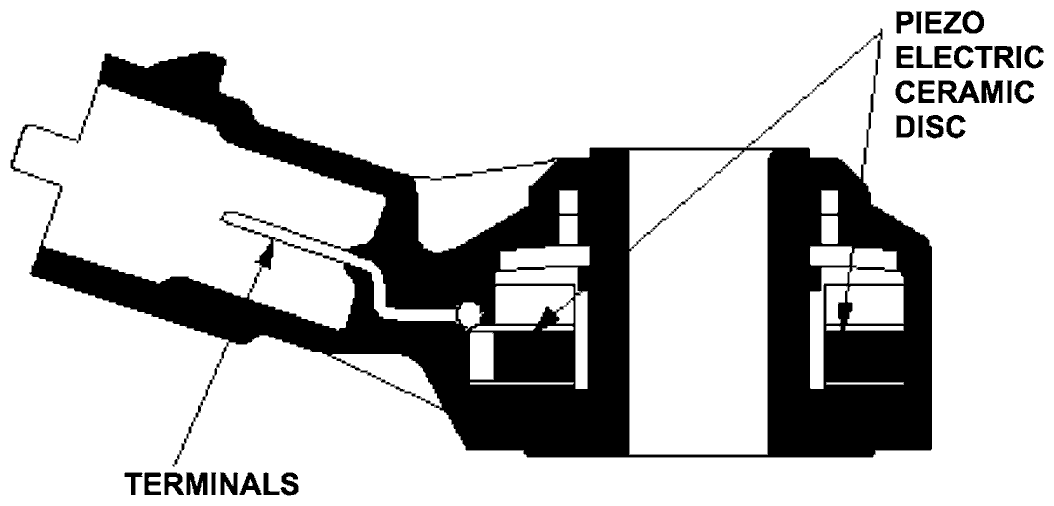
Primary Heated Oxygen Sensor (Primary HO2S)
The primary HO2S detects the oxygen content in the exhaust gas and sends signals to the ECM which varies the duration of fuel injection accordingly. To stabilize its output, the sensor has an internal heater. The primary HO2S is installed in the exhaust manifold. By controlling the air fuel ratio with primary HO2S and secondary HO2S, the deterioration of the primary HO2S can be evaluated by its feedback period. When the feedback period exceeds a certain value during stable driving conditions, the sensor is considered deteriorated and the ECM sets a DTC.
Secondary Heated Oxygen Sensor (Secondary HO2S)
The secondary HO2S detects the oxygen content in the exhaust gas downstream of the Three Way Catalytic Converter (TWC) and sends signals to the ECM which varies the duration of fuel injection accordingly. To stabilize its output, the sensor has an internal heater. The secondary HO2S is installed in the TWC.
Starting Control
When the engine is started, the ECM provides a rich mixture by increasing injector duration.Vehicle Speed Sensor (VSS)
The VSS is driven by the differential. It generates a pulsed signal from an input of 5 volts. The number of pulses per minute increases/decreases with the speed of the vehicle.Electronic Throttle Control System
The throttle is electronically controlled by the electronic throttle control system. Refer to the System Diagram to see the functional layout of the system.
Idle control: When the engine is idling, the ECM controls the throttle actuator to maintain the proper idle speed according to engine loads.
Acceleration control: When the accelerator pedal is pressed, the ECM opens the throttle valve depending on the accelerator pedal position (APP) sensor signal.
Accelerator Pedal Position (APP) Sensor
As the accelerator pedal position changes, the sensor varies the signal voltage to the ECM.
Throttle Body
The throttle body is a single-barrel side draft type. The lower portion of the throttle valve is heated by engine coolant from the cylinder head to prevent icing of the throttle plate.
Idle Control System
When the engine is cold, the A/C compressor is on, the transmission is in gear, the brake pedal is pressed, or the alternator is charging, the ECM controls current to the throttle actuator to maintain the correct idle speed.
Brake Pedal Position Switch
The brake pedal position switch signals the ECM when the brake pedal is pressed.Fuel Supply System
Fuel Cut-off Control
During deceleration with the throttle valve closed, current to the injectors is cut off to improve fuel economy at speeds over 1,160 rpm (min-1). Fuel cut-off action also occurs when engine speed exceeds 6,200 rpm (min-1), regardless of the position of the throttle valve, to protect the engine from over-revving. When the vehicle is stopped, the ECM cuts the fuel at engine speeds over 6,200 rpm (min-1).Fuel Pump Control
When the ignition is turned on, the ECM grounds the PGM-FI main relay which feeds current to the fuel pump for 2 seconds to pressurize the fuel system. With the engine running, the ECM grounds the PGM-FI main relay and feeds current to the fuel pump. When the engine is not running and the ignition is on, the ECM cuts ground to the PGM-FI main relay which cuts current to the fuel pump.PGM-FI Main Relay 1 and 2
The PGM-FI relay consists of two separate relays. The PGM-FI main relay 1 is energized whenever the ignition switch is ON (II) which supplies battery voltage to the ECM, power to the injectors, and power for the PGM-FI main relay 2. The PGM-FI main relay 2 is energized to supply power to the fuel pump for 2 seconds when the ignition switch is turned ON (II), and when the engine is running.Catalytic Converter System
Three Way Catalytic Converter (TWC)
The TWC converts hydrocarbons (HC), carbon monoxide (CO), and oxides of nitrogen (NOx) in the exhaust gas to carbon dioxide (CO2), dinitrogen (N2), and water vapor.
Exhaust Gas Recirculation (EGR) System
Refer to the System Diagram to see the functional layout of the system.
EGR Valve
The EGR valve lowers peak combustion temperatures and reduces oxides of nitrogen emissions (NOx) by recirculating exhaust gas through the intake manifold and into the combustion chambers.Positive Crankcase Ventilation (PCV) System
The PCV valve prevents blow-by gasses from escaping into the atmosphere by venting them into the intake manifold.
Evaporative Emission (EVAP) Control System
Refer to the System Diagram to see the functional layout of the system.
EVAP Canister
The EVAP canister temporarily stores fuel vapor from the fuel tank until it can be purged back into the engine and burned (refer to the System Diagram to see the functional layout of the system).EVAP Canister Purge Valve
When the engine coolant temperature is below 40°C (104°F), the ECM turns off the EVAP canister purge valve which cuts vacuum to the EVAP canister.Electronic Throttle Control System Diagram
The electronic throttle control system consists of the throttle actuator, throttle position (TP) sensor, accelator pedal position (APP) sensor, throttle actuator control module, and the ECM. The throttle is electronically controlled by this system.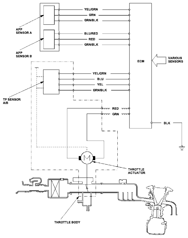
Exhaust Gas Recirculation (EGR) System Diagram
The EGR system reduces oxides of nitrogen (NOx) emissions by recirculating exhaust gas through the EGR valve and the intake manifold into the combustion chambers. The ECM memory includes the ideal EGR valve position for varying operating conditions.
The EGR valve position sensor detects the amount of EGR valve lift and sends it to the ECM. The ECM then compares it with the ideal lift in its memory (based on signals sent from other sensors). If there is any difference between the two, the ECM cuts current to the EGR valve.
Evaporative Emission (EVAP) Control Diagram
The EVAP controls minimize the amount of fuel vapor escaping to the atmosphere. Vapor from the fuel tank is temporally stored in the EVAP canister until it can be purged from the EVAP canister into the engine and burned.
- The EVAP canister is purged by drawing fresh air through it and into a port on the intake manifold.
The purging vacuum is controlled by the EVAP canister purge valve, which operates whenever engine coolant temperature is above 40°C (104°F). - When vapor pressure in the fuel tank is higher than the set value of the EVAP two way valve, the valve opens and regulates the flow of fuel vapor to the EVAP canister.
